Large Format 3D Printers Hardware Configuration
Using PrintWatch AI on a large format 3D printer requires additional steps to set up properly. You cannot just throw a camera onto a large format printer and expect it to detect defects accurately. Since the print bed area that is being monitored is significantly larger, the amount of pixels in the frame representing a possible defect will be significantly less. This can be addressed in a multitude of ways described below.
Camera Setup
Resolution: The Camera should produce a good quality image of the print bed area. For Large Format 3D Printers it is recommended to use an 8MP camera that produces good quality images. We recommend using a Sony IMX179 Sensor or similar.
Quality: The camera streamer has a quality setting that ranges from 0-100, with 100 being the best quality. It is recomended to run the camera in a quality of 100 or as close to 100 as possible, with the absolute minimum being a quality of 80.
Framerate: The camera framerate (FPS) does not need to be high in order to run the AI. The AI software analyzes the current image every 10 seconds. A frame rate of 1 frame per second is sufficient to run the AI software, however it is recomended to use a frame rate of 5 frames per second to run the AI software.
How the image is processed for the ML model
One thing to keep in mind with the camera configuration is that the images are resized to 640 x 640 pixels when being analyzed by the ML model. If the Camera is mounted at a distance away from the print bed, this will mean that small to medium details will not be seen and the ML model will only be able to detect large failures. For this reason, it is ideal to place the camera as close to the bed as possible while maintaining a full view of the print area.
The slicing ability helps address the quality loss due to image resizing. Slicing allows for us to specify regions within a frame that we want to be analyzed. For example, this allows us to select a 640 x 640 pixel region inside of a 3840x2160 image that we want monitoring to occur (everything outside of the region is ignored). This would in result in no image quality loss for the 640x640 region that will be analyzed by the ML model.
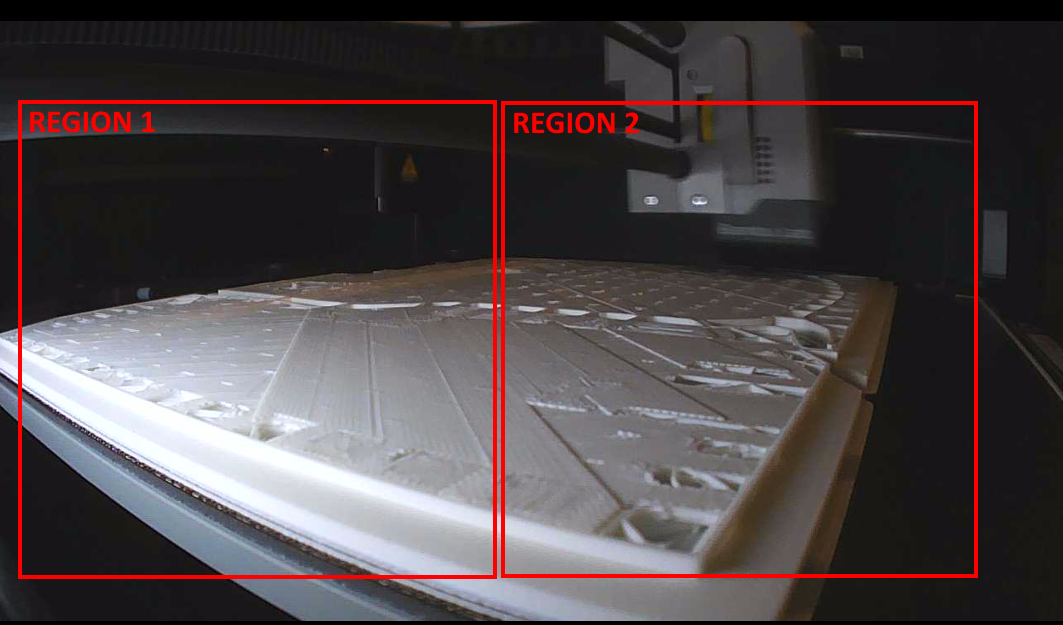
With large format printers, we add 2-4 monitoring regions to our 3840x2160 image frame. This helps maintain the original quality of the camera that is being used to monitor the printer. Otherwise, when we resize the image from 3840x2160 -> 640x640, we can lose up to 95% of the details captured by the original camera, leading to a similar amount of loss in performance for the ML model.
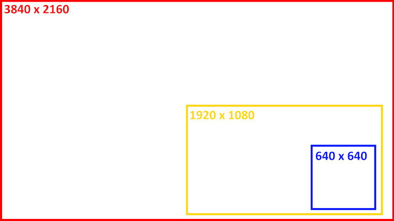
For Reference, here is a visual of how much the image is resized prior to being analyzed by the ML model if you are analyzing the entire 3840x2160 frame:
Example of how slicing helps
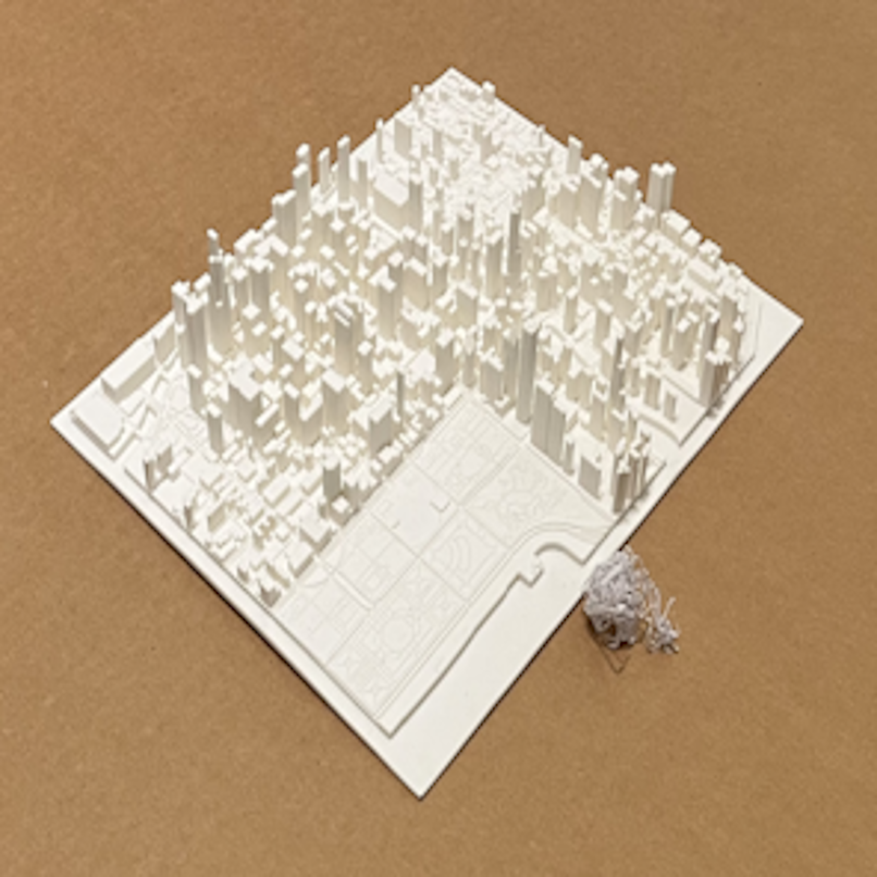
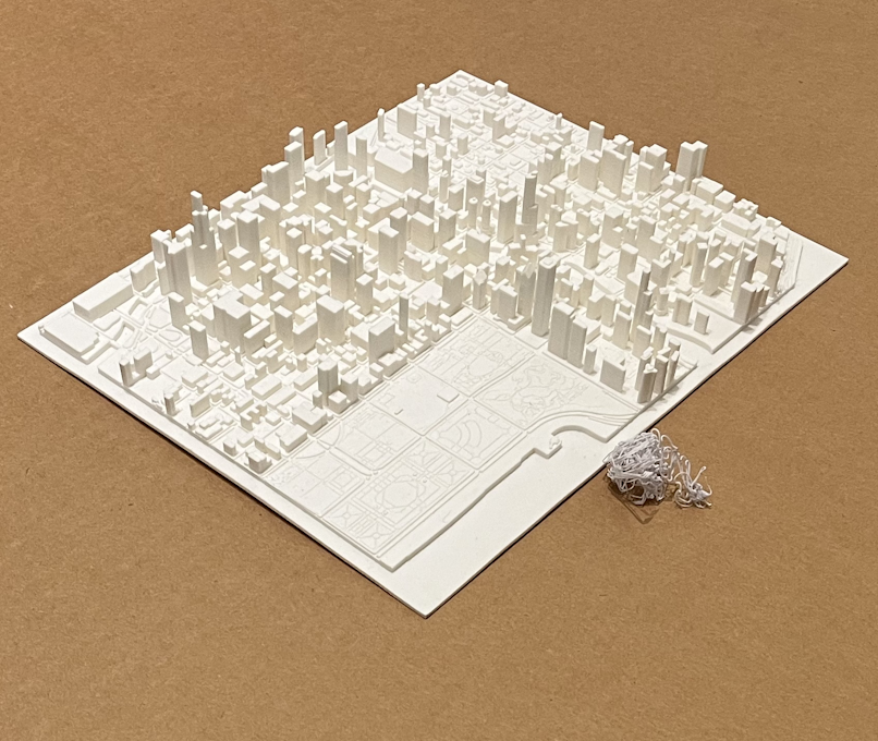
In this example we are using a 4032x3024 camera on a 660 x 760 mm print bed. There is a spaghetti defect of diameter 40mm placed next to a printed map. The top image is the preview with the original image before any processing is done:
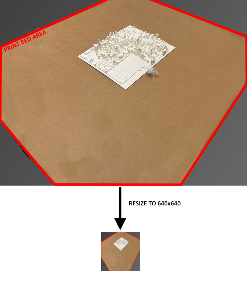
The bottom image is how much smaller the resized image is.
After resizing the full image to 640x640 this is a close-up of the smaller image, take note of the quality of the items in the frame:
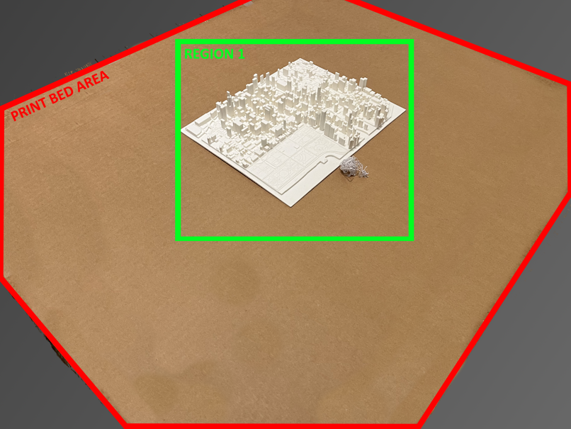
To fix this we use slicing. The green boxed region shown below is monitored:
As a result, this is a close-up of the sliced region when it is resized to 640x640 and analyzed by the ML model, take note of the quality once again:
Multiple cameras
Use of multiple cameras is beneficial if the entire print bed is not visible using a single camera. Keep in mind that for ML model performance, the most important factor is the use of slicing and ensuring that the camera is capturing enough detail inside of a 640 x 640 frame.
Position
Position the Camera to:
- Keep the entire print bed and print area within frame
- Maximize the print bed and print area in the frame
- Ideally print bed and area are edge-to-edge in the camera frame
- Remove items in the background/outside the printer in the Camera frame
- These may cause false-Positive detections
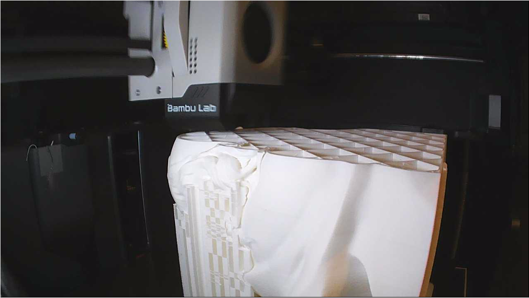
The BambuLabs printers are a good example of camera placement (model P1S pictured):
Lighting
- The print bed and print area should be well-lit and visible with the human eye
- The rule of thumb for Computer-Vision based AI is that if a person is unable to clearly see what is in the frame, then neither will the AI.
- Do not over-expose the print bed and print object with too much light
- A good balance between well-lit and not too bright is required (see examples below).
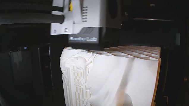
Good Example: Object is visible, and not overexposed to light
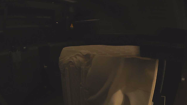
Bad Example: Not enough lighting, object is not clearly visible
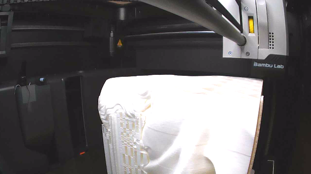
Bad Example: Too much lighting, object is overexposed
Extras
If there are items within the print chamber that are causing issues with the AI software, such as False-Positives, they can be addressed in two ways:
- Sample images from the camera inside the printer enclosure and train with it to cancel out the False-Positives
- Add blockout regions inside the AI software.
- A blockout region replaces the selected camera frame areas with black pixels when being sent to the AI model, essentially removing the item from the frame
- This does not change the camera stream or stream preview
Example of #2
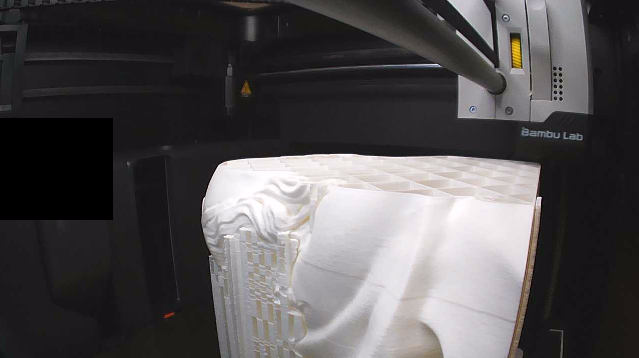
The purge shoot on the BambuLabs may get some pieces of spaghetti stuck and visible inside of the frame, and this may cause the AI to unwantingly detect it:
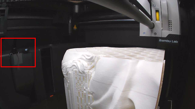
The AI software will draw over the selected area with black pixels so the AI model ignores anything in this region: